
How to Install and Configure Motherboards, CPUs, and Add-on Cards for CompTIA A+ Core 1 (220-1101)
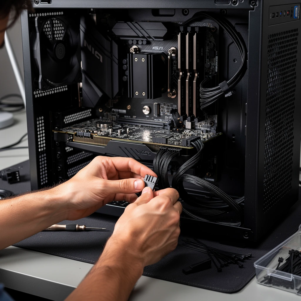
1. Why This A+ Objective Matters
For CompTIA A+ Core 1, this is one of those objectives where you really do have to get your hands dirty. You’re expected to identify the hardware, install it properly, and then catch the usual mistakes that pop up when compatibility, power, firmware, or cabling gets missed. In real support work, motherboard, CPU, and add-on card problems usually don’t fail in some dramatic, obvious way right out of the gate. More often, the system powers on, the fans spin, and somebody figures the job’s done, even though the machine never finishes POST, never sees the device, or starts overheating five minutes later.
The exam tests that same thinking. It’s not enough to just recognize what a PCIe slot or 24-pin connector looks like. You need to identify what changed, verify compatibility before replacing parts, and distinguish between power on, successful POST, and successful OS boot. Those aren’t the same stage at all. A machine can get power and still fail POST, and it can pass POST just fine but still refuse to boot an operating system.
2. Motherboard Basics and Compatibility
The motherboard is basically the main platform everything else hangs off of — CPU, memory, storage, onboard controllers, and expansion cards. It also sets a lot of the system’s limits: which CPU families are supported, what kind of RAM you can use, storage options, PCIe layout, internal headers, and how much power the system needs. For A+, the safest rule is simple: socket match is necessary, but not sufficient. The motherboard vendor’s CPU support list and required BIOS/UEFI version are authoritative.
Common form factors
- ATX - 12 x 9.6 in; more expansion slots, headers, and service room
- Micro-ATX - 9.6 x 9.6 in; fewer slots, common in business desktops
- Mini-ITX - 6.7 x 6.7 in; compact, limited expansion
Form factor affects whether the board fits the case, where the standoffs go, how the rear I/O lines up, and how much room you’ve got for expansion. A board might physically fit the case and still be a bad match if a big GPU chokes airflow, the PSU doesn’t have the right connectors, or the case can’t handle the cooler height.
CPU, chipset, and firmware support
Modern platform compatibility comes down to socket type, board design, firmware support, and the platform’s built-in limits. At A+ level, think of chipset and platform differences as affecting features such as PCIe lanes, USB support, SATA availability, RAID support, and business versus performance features. But for actual CPU support, always verify the vendor CPU support matrix and BIOS version requirement.
Also remember socket handling differs by platform. Many Intel desktop boards use LGA sockets with contacts on the motherboard. Older AMD consumer platforms commonly used PGA CPUs with pins on the processor, while newer AMD AM5 is also LGA. That matters when handling parts because bent pins or damaged socket contacts can cause no POST, missing memory channels, or intermittent faults.
Memory compatibility basics
RAM must match the board’s supported DDR generation exactly. DDR4 and DDR5 are not cross-compatible. Mixed modules may force lower speeds or timings and can create instability. Some platforms support ECC memory and some don’t, and a lot of consumer boards expect non-ECC DIMMs anyway. Install the memory in the paired slots the board manual calls for if you want dual-channel to work properly.
Storage and M.2 awareness
M.2 is a form factor, not a guarantee of NVMe. Depending on how the motherboard’s wired and what the firmware supports, an M.2 slot might accept SATA, PCIe/NVMe, or both — and yeah, that detail matters a lot more than people expect. NVMe is basically the communication method that lets a solid-state drive talk over PCIe efficiently. A really common exam mistake is assuming any M.2 drive will work in any M.2 slot. It doesn’t. An M.2 SATA SSD will not work in an M.2 slot that supports only PCIe/NVMe, and the reverse can also be true.
Some motherboards share lanes between M.2 slots, SATA ports, and PCIe slots, so using one feature can actually disable another one or cut its bandwidth down. It's not broken — it's just how the board is laid out. For example, on some boards, installing a drive in one M.2 slot might shut off SATA port 5 or 6, or it might make a secondary PCIe slot run slower than you expected. The motherboard manual beats memory here, every time. That’s not a defect — it’s just how the board is wired. That’s not a defect — it’s a design limitation, and the manual usually spells it out.
Common ports, headers, and power connectors
On the rear I/O, you’ll usually see the usual suspects: USB-A, USB-C, RJ-45, audio jacks, HDMI, DisplayPort, and sometimes PS/2 if the board is a little old-school. Inside the board, you’ll usually find headers for the front-panel buttons and LEDs, USB 2.0, USB 3.x 19-pin, front audio, CPU fan, system fan, pump connections, and sometimes TPM or RGB/ARGB. It sounds like a lot, but once you’ve done a few builds, it starts to make sense pretty quickly.
- 24-pin ATX main board power, often seen as 20+4 on modular PSUs
- CPU power 4-pin, 8-pin, or 4+4 EPS12V/ATX12V near the CPU socket
- SATA ports for SATA SSDs, HDDs, and some optical drives
- Front-panel header for power switch, reset switch, power LED, drive LED
- USB headers for front-panel USB ports
- Audio header for front headphone and microphone jacks
Power switch and reset switch polarity usually does not matter. LED polarity does. Also, motherboard ATX power, CPU EPS power, and PCIe GPU power are keyed differently and should never be forced or interchanged.
Integrated vs. discrete graphics
Motherboard video outputs function only when the platform supports integrated graphics output and the installed CPU includes integrated graphics. Some systems also disable or deprioritize onboard video when a discrete GPU is installed unless firmware settings are changed.
Quick compatibility workflow
- Match board form factor to case and standoff locations
- Verify CPU socket, vendor CPU support list, and required BIOS version
- Confirm RAM type, supported capacity, and slot population order
- Before you install anything, double-check storage support carefully. SATA, M.2 SATA, M.2 NVMe, and boot support aren’t always the same thing, and that’s exactly the kind of detail that’ll bite you if you skim past it. Seriously, this catches a lot of people.
- Make sure the PSU has enough wattage and, just as important, the right ATX, EPS, and PCIe connectors for the hardware you’re installing. The connector check matters just as much as the wattage check. I’ve seen more than one upgrade get stuck because somebody checked the wattage and completely forgot to verify the connectors.
- Review lane-sharing notes, disabled ports, and slot bandwidth limits
- CCheck the cooler socket kit, cooler height, and RAM clearance before you get started.
3. Safety, prep, and documentation — this is the part that keeps the job from turning into a mess.
Before you touch anything, unplug the AC power cord and switch the PSU off if it’s got a power switch. Pressing the power button after unplugging can help bleed off leftover power, but don’t assume the system’s fully discharged right away. Give it a moment and don’t rush that step. Use ESD precautions, hold the board by the edges, and never plug in or remove internal parts while the system’s powered on. That's basic bench discipline, and it saves hardware. Don’t force it. Ever. Ever. Ever. Ever.
Lay out the screws, standoffs, brackets, and cables before you even start. It’ll make the whole job a lot smoother. It saves time, and it keeps you from digging around for tiny parts halfway through the install. Trust me, that gets old fast. In a professional environment, I’d always document the original configuration, firmware version, model number, and any BIOS or UEFI settings you change before you touch anything. That way, if something goes sideways later, you’ve got a clean baseline to work from. That’s a big deal when you’re troubleshooting. That's really important for rollback, warranty support, and change control. In enterprise work, that's not optional — it's just good practice.
4. Installing the Motherboard
- Verify the case supports the board form factor.
- Check standoff locations against the board mounting holes.
- If the board doesn’t have an integrated I/O shield, install the separate one first.
- Lower the board into place and line up the rear ports and standoffs carefully.
- Secure the board, but don’t crank the screws down too hard.
- Connect the 24-pin ATX power lead and the CPU EPS power lead.
- Connect front-panel switch and LED headers, USB, audio, and fan headers.
- If you're using SATA storage, go ahead and connect the data and power cables before you close the case up. It’s easier than reopening everything later.
- Before you call it done, check for loose screws, pinched cables, and anything that might be blocking a fan. That last visual check catches more problems than people think.
Standoffs matter because one extra standoff under the board can short the traces and cause no-POST problems or weird intermittent shutdowns. I've seen that exact mistake turn a simple build into a headache. Front-panel headers are another place people trip up all the time, so use the board diagram instead of guessing.
5. Installing the CPU and cooler
CPU installation changes a bit depending on the socket and vendor design, but the basics don’t change: verify support first, line up the orientation marks, never force the CPU, and mount the cooler evenly. Thermal interface material is required between the CPU heat spreader and cooler base, either as pre-applied material on the cooler or as manually applied thermal paste.
CPU and cooler checklist
- Correct socket and vendor support list match
- Required BIOS/UEFI version confirmed
- Cooler includes the correct mounting bracket or backplate
- Cooler TDP rating is appropriate for the CPU
- Cooler height fits the case and clears nearby RAM if applicable
Installation workflow
- Open the retention mechanism.
- Align triangle or notch markers and place the CPU gently.
- Lock the retention arm or frame.
- If needed, apply a small manufacturer-appropriate amount of thermal paste.
- Mount the cooler evenly using the correct bracket or backplate.
- Connect the fan to CPU_FAN unless the cooler instructions specify otherwise.
If you need to remove and reapply paste, clean off the old material with isopropyl alcohol and a lint-free cloth before you start over. Don’t just stack new paste on top of old paste. The common mistakes are bent pins or socket contacts, forgetting to peel the protective film off the cooler, mounting it unevenly, and plugging the cooler fan into a system fan header instead of CPU_FAN. Those are the classic bench mistakes, honestly. A BIOS reading of 0 RPM is usually a warning sign, although some systems, pumps, or fan-stop features can report it differently. So, yeah, don't panic immediately — verify the setup first.
6. Power Supply Considerations
Connector presence is not enough. The PSU must also provide sufficient wattage and adequate 12V capacity for the CPU and GPU. This becomes important after upgrades, especially discrete graphics cards.
- 24-pin ATX powers the motherboard
- 4+4 EPS12V commonly powers the CPU
- PCIe GPU power may use 6-pin, 8-pin, 6+2-pin, or newer 12VHPWR/12V-2x6 connectors
Don’t assume adapters solve every mismatch. If a GPU requires connectors your PSU was never designed to provide, the safer answer may be a PSU upgrade. This is especially relevant in OEM desktops, where proprietary PSUs, limited wattage, or nonstandard connectors can block otherwise simple upgrades.
7. Add-on Cards and PCIe Basics
Add-on cards include GPUs, NICs, wireless adapters, sound cards, USB controllers, capture cards, and RAID or storage controllers. Most modern systems use PCIe. Slot length and electrical bandwidth are related but not identical: a slot may be x16 length physically but wired for fewer lanes electrically, such as x4.
PCIe cards often work in larger compatible slots, and some open-ended slots can take longer cards if the board and case allow it. But performance and functionality still depend on the electrical wiring, firmware support, and lane sharing. PCIe generations are backward compatible in principle, though the device runs at the highest mutually supported speed.
Installation workflow
- Confirm slot type, lane requirements, and physical clearance.
- Check bracket type: full-height or low-profile.
- Power down and unplug the system.
- Remove the correct slot cover and seat the card fully.
- Secure the bracket and, if the card needs it, connect the auxiliary power lead before you try to boot. A surprising number of no-display calls come down to that one missed cable.
- Boot the system, check detection in BIOS or UEFI if needed, and then install the drivers in the operating system once you know the hardware is actually seen. No point installing drivers for hardware the board isn't even detecting yet.
For GPUs, the best slot is usually the primary graphics slot listed in the motherboard manual, which is often the top x16-length slot — though board layouts can vary, so always verify. Large cards can block nearby slots and cut down airflow. For RAID, NIC, and GPU devices, you may still need the manufacturer’s drivers or firmware even if the OS loads a generic driver at first.
Older standards like PCI, AGP, and riser cards can still show up on the exam as awareness-level distractors.
8. Checking BIOS/UEFI, updates, and recovery
After installation, BIOS or UEFI is the first place you should verify everything. Check that the CPU model, RAM amount, storage devices, and temperatures all look reasonable. Then verify boot order and onboard device settings.
- CPU detected correctly
- Expected RAM amount and slot population shown
- SATA and NVMe devices detected
- Primary display setting appropriate for integrated or discrete graphics
- Fan monitoring and temperature readings normal
- Boot mode and device order correct
At a basic level, also recognize settings such as UEFI vs Legacy/CSM, AHCI vs RAID, Secure Boot, and optional memory profiles such as XMP/EXPO. Those may affect boot behavior or expected memory speed.
Firmware update basics
If an older board doesn’t recognize a newer CPU, you might need a BIOS or UEFI update before it’ll cooperate. That’s a pretty common compatibility issue. Use the exact motherboard model and revision, get firmware only from the manufacturer, and never interrupt power during the update. Firmware updates are useful, but they deserve respect. That part’s absolutely crucial. Some boards support recovery or update features like BIOS Flashback or Q-Flash Plus, and those can be a lifesaver when you don’t have an older supported CPU available just to get the system to boot.
Recovery and reset
If hardware changes prevent POST, loading BIOS defaults or clearing CMOS can help. Use the board’s jumper or button procedure or follow the manufacturer’s instructions. This is a troubleshooting step, not a random habit: do it when firmware settings may be blocking normal detection or boot.
9. POST Indicators and Validation
Not all systems use beep codes. Some use debug LEDs, POST code displays, or vendor-specific indicators. Learn the sequence:
- No power - no fans, no LEDs, nothing responds
- No POST - powers on but fails hardware initialization
- No boot - POST succeeds but no operating system loads
- No display - may be a video path issue even if POST succeeds
After installation, validate the hardware in BIOS or UEFI first, then check it again in the operating system. That two-step check catches a lot of issues early. In Windows, use Device Manager, msinfo32, and dxdiag as quick checks. In Linux, tools such as lspci, lsblk, and dmesg provide similar confirmation. A detected device with a generic driver isn’t always fully configured, and chipset, GPU, wireless, and RAID devices usually work best with the manufacturer’s drivers.
10. Troubleshooting workflow — this is where staying calm and methodical really pays off.
Use a structured order: Power → Seating → Compatibility → Firmware → Drivers → Validation. Change one thing at a time and reduce the build to minimum hardware when needed.
Minimum boot test
If a system won’t POST after a motherboard or CPU change, strip it down and test with just the motherboard, CPU, cooler, one known-good DIMM in the recommended slot, the PSU, and the video path if you need it. If you suspect a short, breadboard the system outside the case on a nonconductive surface so you can rule out standoff or chassis problems.
Quick symptom-to-cause guide — a handy way to narrow things down when the system’s acting up.
- Fans spin, no display: wrong display output, unpowered GPU, unsupported CPU or BIOS, loose RAM, unseated card
- No POST after board install: missing EPS cable, extra standoff, front-panel miswire, loose DIMM, incompatible firmware
- CPU overheats quickly: no thermal interface material, protective film left on cooler, uneven mount, wrong fan header, failed fan
- Add-on card not detected: wrong slot, lane-sharing limitation, not fully seated, missing driver, onboard conflict
- Instability under load: weak PSU, overheating, poor airflow, loose CPU or GPU power connector
Known-good part substitution remains one of the fastest isolation methods. So does visual inspection for bent socket contacts, damaged pins, and partially seated cables.
11. Security and Service Considerations
Use manufacturer-approved firmware only, and be careful with used or refurbished boards, especially if you don’t know the firmware history. Be aware of BIOS or UEFI passwords, Secure Boot, and TPM or fTPM settings, because they can affect deployment and boot behavior after a board replacement. In business environments, document serial numbers, firmware versions, installed components, and any settings you changed during service.
12. Exam-Focused Review
What CompTIA wants you to notice in scenario questions is usually one of these:
- Correct socket does not guarantee supported CPU
- Fans spinning does not mean POST succeeded
- Motherboard video output does not work without supported integrated graphics
- M.2 form factor does not guarantee NVMe compatibility
- A card fitting in a slot does not guarantee best slot choice or full bandwidth
- Missing CPU EPS or GPU auxiliary power is a classic no-display trap
High-yield memorization list
- ATX 12 x 9.6, Micro-ATX 9.6 x 9.6, Mini-ITX 6.7 x 6.7
- 24-pin ATX vs 4+4 EPS12V vs PCIe GPU power
- PCIe x1, x4, x8, x16
- M.2 SATA vs M.2 NVMe
- POST vs boot vs display problem
- Clear CMOS and minimum boot as key troubleshooting steps
Rapid review cram sheet
- Read the motherboard manual before installation
- Verify case, board, PSU, CPU, RAM, and storage compatibility first
- Check the vendor CPU support list and BIOS version
- Use the correct standoffs only
- Connect both 24-pin ATX and CPU EPS power
- Install RAM in the recommended slots for dual channel
- Do not confuse M.2 form factor with NVMe protocol
- Expect lane sharing on some boards
- Use the correct PCIe slot and bracket type for add-on cards
- Connect GPU auxiliary power when required
- Use CPU_FAN for the processor cooler
- Thermal interface material is required, pre-applied or manual
- Check BIOS/UEFI for CPU, RAM, storage, fan RPM, and temperatures
- Use manufacturer firmware files only
- Clear CMOS if settings may be blocking POST after changes
- Use minimum hardware testing when troubleshooting
- Install manufacturer drivers when generic OS drivers are not enough
- Document what changed and verify the system under load
If you keep the troubleshooting order in mind and treat compatibility as a process instead of a guess, you will be in good shape for both the exam and real bench work.